Let me begin by saying that this is my first ever experiment with Raspberry Pi, rather IOT. It was a fun ride! When I started exploring Raspberry Pi projects, Home Automation seemed the best use of the power of Raspberry Pi. So, I asked my self what would I love to automate in my home?
I am lousy at remembering to turn off electrical devices after I have used them. It’s not ignorance per say but I just forget many times. That’s when I thought if I could hook up my Raspberry pi to my electric boiler or Microwave oven and be able to shut it down remotely. That would be awesome! So I made this prototype project. I wanted to experiment with an electric bulb which runs on AC supply but this being my first project of handling electrical devices and after reading several warnings on the internet, I decided to stick to high voltage LED (9-12 Volts).
Here is what I decided to do:
To control a 9 volt LED powered by external DC supply, using Raspberry Pi and a Relay module. (For devices running on AC, the DC supply would be replaced by AC mains. All other connections and implementation would remain the same)
Apart from turning the device ON and OFF I also added a functionality to send an email when the device stays ON for too long. So if at all forget to turn the device OFF and go to work I would get an email saying “The device has been ON for too long. Please shut it down.” I can then go on the web module and turn it OFF remotely. Awesome use of technology for an airhead like me!
I hope I excited you enough now, to read how did I achieve this. Let’s get to it then. Here’s what you’ll need :
- Raspberry Pi 2 (Details)
- Windows IoT core (Get Started)
- A relay module (5V 10A 2 Channel Relay Module Shield)
- 9 Volts DC battery
- 9-12V LED
I presume, since you are reading this blog you must be aware of what Raspberry Pi and windows IoT are. If not, you can go through above links. I will not be going through setting up windows IoT on your Raspberry Pi and all since we have a lot of ground to cover here. If you visit above link you will get all the details you need. I will however enlist a couple of problems I ran into and their solutions. As far as the relay module is concerned, I will explain it’s role in this project. To further read about it’s working you will get a lot of good articles/videos on the internet.
The Relay Module
A relay, simply put, is a switch which when closed completes a circuit. It is driven by electricity. In Raspberry Pi’s get started tutorial you must have seen a “Blinky” (turn small LED ON and OFF) project. Normal LED requires about 2V to turn ON, so Raspberry Pi on it’s own can light that LED up. But for a 9V LED or if we consider our practical example of an electrical device which runs on 230 Volts supply, Raspberry Pi is not enough. So we use an external supply (DC battery or AC mains) to power the device and introduce a relay in the circuit. This relay is driven by Raspberry Pi’s GPIO pin (GPIO pin usage). So when relay closes the switch the circuit gets completed and the device receives the current from the external supply and starts functioning. Similarly, when relay switch is open, the circuit breaks and device gets turned OFF. You can use a single relay instead of the 2 channel module that I have used. The module I have used has on-board pins which allows connections to be made easily with jumper wires and avoids mounting the relay on breadboard or the need of soldering.
Three output terminals of the relay:
- COM : It is the center terminal
- NC: Normally Closed terminal, this terminal is normally in contact with the central terminal
- NO: Normally Open terminal, this terminal is normally not in contact with the central terminal
When the input terminal of the relay changes from one state to another (high to low or vice versa) a movable armature toggles between NC and NO thus completing or breaking the circuit on the output side. You can read detailed working of relay here.
The Circuit
Here is the circuit diagram. Due to my poor skills of drawing diagrams in Visio or any other tool, I have uploaded a snapshot of a hand-drawn circuit. Please excuse me for that. 😦

Connections :
- Connect GPIO pin 5 to IN1 pin of the relay module
- Connect JD-Vcc of the Relay Module to the positive terminal of the DC battery and GND to the negative (Yes, we are powering the relay from the battery because the RPi cannot generate the current required by the relay to function) Internally JD-Vcc connects to a photosensitive transistor on the board which needs higher current.
- The Vcc terminal on relay board connects internally to an LED which will emit light to activate the photosensitive transistor which will in turn make the armature toggle. This Vcc pin is connected to 5V Vcc pin on RPi and GND pin next to it is connected to GND of RPi
- On the output side of the relay, connect the positive terminal of the DC supply to COM
- Connect positive line from the LED to NO
- Negative line from LED is connected to negative terminal of Battery directly
So when GPIO pin of the RPi is set to high, it changes voltage to 3.3V which sets the IN1 pin of the relay board to HIGH, this turns ON the LED on the board which activates the photosensitive transistor that in turn allows the current from JD-Vcc terminal to flow through the electric coil storing the energy in coil which moves the armature from NC terminal to NO terminal completing the circuit between the DC battery and the LED, turning the LED ON.(I have not explained the relay working in very detail here, you can go through the above link and try and understand it yourself if you want)
The Code
I have used Node.js to run a small web server on Raspberry Pi. The idea is to set the GPIO pin to HIGH when the web server receives a request with query string parameter ‘state=ON’ and set it to LOW when ‘state=OFF’.
I used the basic node.js web server template from visual studio 2015. While creating a new project, go to templates under javascript you will be able to select a “Basic Node.js Web Server” template. It will create a project with server.js file which has the code for you server. Then you can add following code in server.js:
var http = require('http');

var url = require('url');

var uwp = require("uwp");

uwp.projectNamespace("Windows");

var gpioController = Windows.Devices.Gpio.GpioController.getDefault();

var pin = gpioController.openPin(5);

pin.setDriveMode(Windows.Devices.Gpio.GpioPinDriveMode.output);

http.createServer(function (req, res) {

//get the query string (https://nodejs.org/api/http.html#http_message_url)

var queryObject = url.parse(req.url, true).query;

console.log(queryObject);

var pinValue;

if (queryObject && queryObject.state) {

if (queryObject.state.toUpperCase() === "ON") {

pinValue = Windows.Devices.Gpio.GpioPinValue.low;

}

else {

pinValue = Windows.Devices.Gpio.GpioPinValue.high;

}

pin.write(pinValue);

}

res.writeHead(200, { 'Content-Type': 'text/plain' });

res.end('pin status is now: ' + pinValue);

}).listen(1337);
In order to make this code work and deploy it to RPi, yo have to follow certain steps:
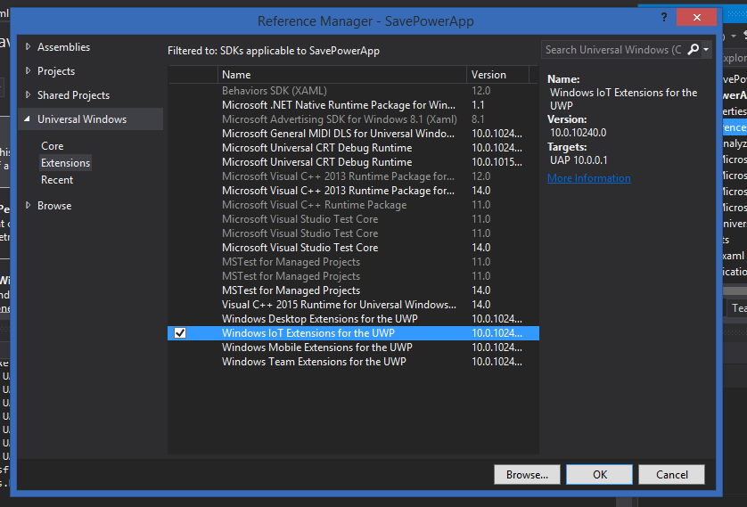
- Add reference to : Windows IoT Extensions for UWP
- Set the IP of RPi in the Project Properties. Also set the platform to ARM
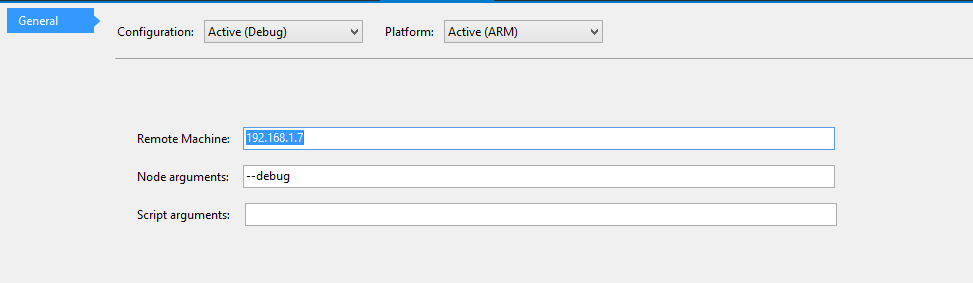
- Go to solution properties and change configuration manager from x86 to ARM. Do the same in debug properties of the Project.

- Now we run the project, Visual studio copies the code to Raspberry Pi and our little RPi is now hosting a web server. Pretty cool, isn’t it?
- Open the browser, type in the your RPi’s IP address in the address bar : “http://192.168.1.7:1337”. since I have used port 1337 I have appended that after colon and hit enter. This will send a request to the web server on RPi, but since we have not sent a query object nothing will happen and it will print undefined
- Now put “http://192.168.1.7:1337/?state=ON” and if your circuit is hooked in correctly, it should toggle your relay and turn your LED ON. Yey!
- You can create a small device controller app (web/mobile) to turn your LED ON and OFF. Just add two buttons on your View and put below code on the click events :
$(document).ready(function () {

$("#btnOn").on("click", function () {

if (!$(this).hasClass("selected")) {

$(this).addClass("selected");

$("#btnOff").removeClass("selected");

var promise = RPiService.changeDeviceState("ON");

promise.success(function () {

$("#response").empty();

$("#response").html("The device was turned on successfully.");

});

}

});

$("#btnOff").on("click", function () {

if (!$(this).hasClass("selected")) {

$(this).addClass("selected");

$("#btnOn").removeClass("selected");

var promise = RPiService.changeDeviceState("OFF");

promise.success(function () {

$("#response").empty();

$("#response").html("The device was turned off successfully.");

});

}

});

});
var RPiService = {};

var RPi_Url = "http://192.168.1.7:1337/" //"http://myproductswebapi.azurewebsites.net/api/products";

RPiService = {

changeDeviceState: function (state) {

//+ "?state=" + state

var jqXhr = $.ajax({

url: RPi_Url + "?state=" + state,

crossDomain: true,

datatype: "jsonp",

success: function (data) {

console.log(data);

}

});

return jqXhr;

}

};

There you go. If you get a static IP for your Raspberry Pi and host your Device controller app on some server, you can control your 9V LED or any device you connect in the circuit from anywhere in the world! Isn’t that amazing?
I have also added a functionality to send an email if the device in the circuit stays ON for too long. I have done this by setting a timeout when the first “ON” request is received and on time out the email is sent to a define email-ID. This way your RPi will remind you to turn OFF the device and you can do so from your web or mobile app, right that second!
You can go through the entire code on GitHub
See it in action here.
I faced a couple of problems in getting this circuit functioning. I want to list them out here hoping it helps someone solve theirs.
THE PROBLEMS
- No Monitor
I did not have a monitor. Getting windows IoT setup without a monitor was quite difficult since it is slave OS, it cannot function on it’s own as a full functioning OS. It needs a machine with windows 10 installed. So I got it installed in my office where I had access to a monitor. Again, you can not remote login to it since it’s not an independent device. Thankfully, Visual Studio 2015 has an option of remote debugging. Since my app did not need any UI I could just remotely deploy it from VS 2015 and get it running. You will need a monitor if you want to develop a UI driven application on Windows IoT. Next problem was to find the IP of RPi on my network. Since I did not have a monitor, I could not see the DefaultApp being launched which displays the IP address of your RPi2. I found 2 solutions to this problem.- The device list in my router’s configuration portal
- Galileo watcher (details)
If at all you cannot access your router’s config portal for some reason, you can install the Galileo watcher. It will list out all the boards connected in your network.
- Getting the relay to work
As I mentioned in the circuit setup it took quite some time for me to figure out that Raspberry Pi won’t be able to provide the required current to the relay on it’s own. I was connecting the two 5V pins from RPi to Vcc and JD-Vcc. The LED on the board would light up but since the JD-Vcc could not provide enough current to photosensitive transistor, the armature wouldn’t move. So make sure that you power up your relay with the external battery.
That’s it for now. Hope you guys enjoyed this blog and I hope you try it out. Do let me know if you try and face any problems in the comments below.
Until next time.
Keep Learning!

can you do this in c sharp with a button on the iot screen
LikeLike
you can create a web server on Rpi with c# http://druss.co/2015/06/raspberry-pi-2-create-c-background-application-on-windows-10/ and using Windows.Devices.Gpio you can read/write to GPIO
var gpio = GpioController.GetDefault();
var pin = gpio.OpenPin(5, GpioSharingMode.SharedReadOnly);
LikeLike
Dear Shweta
Nice project. I am using windows 10 iot core to control my air conditioner remotly. However, I am facing problems regarding infra red library in windows 10 iot core. Will you please help me out?
LikeLike